您现在的位置是:主页 > TYPE-C线缆接线图表 >
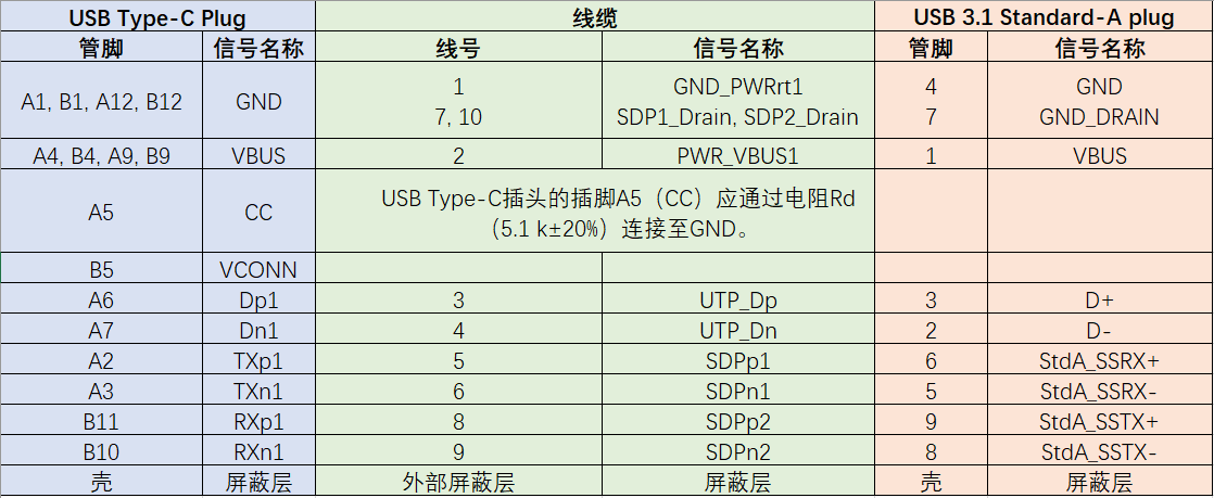
USB TYPE-C和USB3.1 TYPE-A插座适配器线缆接线图
发布时间:2022-12-26 12:20:08所属栏目:TYPE-C线缆接线图表 已帮助人编辑作者:【USB接口百科】


± 20%). See Section 4.5.3.2.1 and Table 4-25 for the functional description and value of Rd.This table that shielded twisted pair is used for all SDP’s
and there are drain wires. If coaxial wire construction is used, then no drain wires are
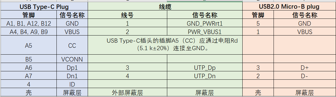
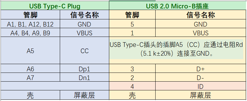
present, and the shields of the coaxial wires are connected to the ground pins.Contacts B6 and B7 should not be present in the USB Type-C plug.All VBUS pins shall be connected together within the USB Type-C plug. A 10 nF bypass
capacitor is required for the VBUS pin in the USB Type-C plug end of the cable. The bypass
capacitor should be placed as close as possible to the power supply pad. A bypass capacitor
is not required for the VBUS pin in the Standard-A receptacle.
5.Shield and GND grounds shall be connected within the USB Type-C plug and USB 3.1 Standard-A receptacle on both ends of the adapter assembly.All USB Type-C plug pins that are not listed in this table shall be open (not connected)
USB信号定义:http://www.usbzh.com/article/detail-206.html
USB接口大全:http://www.usbzh.com/article/detail-144.html
TYPE-C信号定义:http://www.usbzh.com/article/detail-722.html

以上就是USB接口百科为您提供USB TYPE-C和USB3.1 TYPE-A插座适配器线缆接线图的解读,本文章链接: http://www.usb-hub.cn/typecjxt/42216.html 欢迎分享转载,更多婚礼相关资讯请前往TYPE-C线缆接线图表
相关文章
猜你喜欢
USB TYPE-C和USB3.1 TYPE-A插头线缆接线图
USB TYPE-C和USB3.1 TYPE-A线缆接线图: USB信号定义:http://www.usbzh.com/article/detail-2...
USB全功能TYPE-C线缆接线图
This table that coaxial wire construction is used for all SDP’s and there are no drain wires. The ...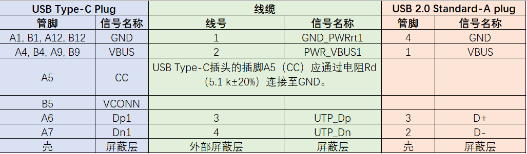
USB TYPE-C和USB2.0 TYPE-A插头线缆接线图
Pin A5 (CC) of the USB Type-C plug shall be connected to VBUS through a resistor Rp (56 kΩ ± 5%)....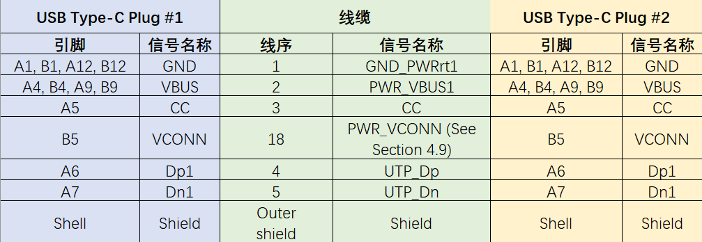
USB2.0TYPE-C线缆接线图
TYPE-C接口也可以只接USB2.0的信号。 Pin B5 (VCONN) of the USB Type-C plug shall be used in...
USB接口百科推荐
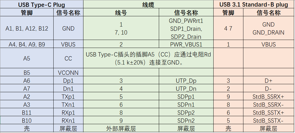
USB TYPE-C和USB3.1 TYPE-B插头线缆接线图
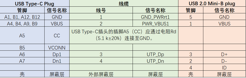
USB TYPE-C和USB2.0 Mini-B插头线缆接线图
-
USB2.0TYPE-C线缆接线图
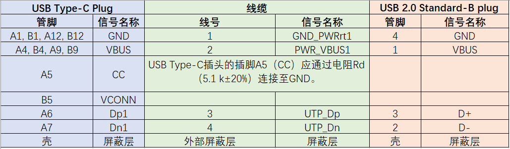
USB TYPE-C和USB2.0 TYPE-B插头线缆接线图
-
USB TYPE-C和USB2.0 TYPE-A插头线缆接线图
-
USB TYPE-C和USB3.1 TYPE-A插座适配器线缆接线图
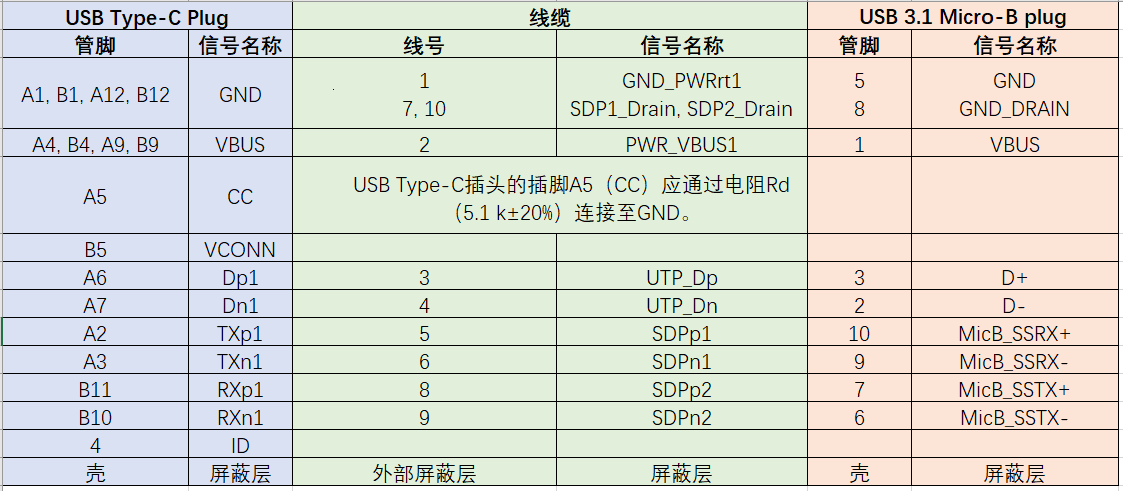
USB TYPE-C和USB3.1 Micro-B插头线缆接线图
-
USB TYPE-C和USB3.1 TYPE-A插头线缆接线图
USB TYPE-C和USB2.0 Micro-B插头线缆接线图
TYPE-C接口形态
-
USB全功能TYPE-C线缆接线图
USB TYPE-C和USB3.1 Micro-B插座适配器线缆接线图